
ファイル:Voyager spacecraft structure.jpg
元のファイル (800 × 1,000 ピクセル、ファイルサイズ: 235キロバイト、MIME タイプ: image/jpeg)
ウィキメディア・コモンズのファイルページにある説明を、以下に表示します。
|
概要

| 解説 |
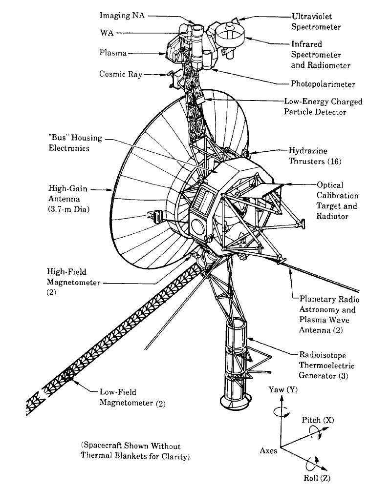
English: The Voyager spacecraft structure - schematic diagram.
The 3.7 metre diameter high-gain antenna (HGA) is attached to the hollow ten-sided polygonal electronics bus, with the spherical tank within containing hydrazine propulsion fuel. The Voyager Golden Record is attached to one of the bus sides. The angled square panel to the right is the optical calibration target and excess heat radiator. The three radioisotope thermoelectric generators (RTGs) are mounted end-to-end on the lower boom. The two planetary radio and plasma wave antenna extend diagonally downwards left and right. The 13 metre long Astromast tri-axial boom extends diagonally downwards left and holds the two low-field magnetometers (MAG); the high-field magnetometers remain close to the HGA. The instrument boom extending upwards holds, from bottom to top: the cosmic ray susbsystem (CRS) left, and Low-Energy Charged Particle (LECP) detector right; the Plasma Spectrometer (PLS) right; and the scan platform that rotates about a vertical axis. The scan platform comprises: the Infrared Interferometer Spectrometer (IRIS) (largest camera at top right); the Ultraviolet Spectrometer (UVS) just above the UVS; the two Imaging Science Subsystem (ISS) vidicon cameras to the left of the UVS; and the Photopolarimeter System (PPS) under the ISS. Suggested for English Wikipedia:alternative text for images: A space probe with squat cylindrical body and a large parabolic radio antenna dish pointing left, a three-element radioisotope thermoelectric generator on a boom extending down, and scientific instruments on a boom extending up. A disk is fixed to the body facing front left. A long tri-axial boom extends down left and two radio antenna extend down left and down right.Polski: Schemat konstrukcji sondy Voyager |
| 日付 | |
| 原典 | The Voyager Neptune Travel Guide |
| 作者 | NASA |
| その他のバージョン |
このファイルの派生的著作物: |
ライセンス
| このファイルはアメリカ航空宇宙局(NASA)によって作成されたものです。NASAの著作権の方針では、特記事項が無い場合、NASAの資料はパブリックドメインとなります。 (詳しくはTemplate:PD-USGov、NASAの著作権の方針について(英語)又はジェット推進研究所(JPL)の画像使用に関するガイドライン(英語)をご覧ください。) |
||
 |
注意事項:
|
ファイルの履歴
過去の版のファイルを表示するには、その版の日時をクリックしてください。
| 日付と時刻 | サムネイル | 寸法 | 利用者 | コメント | |
|---|---|---|---|---|---|
| 現在の版 | 2009年12月4日 (金) 05:10 | | 800 × 1,000 (235キロバイト) | Camilo Sanchez | Reverted to version as of 19:07, 24 July 2008 |
| 2009年12月4日 (金) 05:07 |  | 744 × 1,052 (1,023キロバイト) | Camilo Sanchez | Raster to vector version | |
| 2008年7月24日 (木) 19:07 |  | 800 × 1,000 (235キロバイト) | Mirecki | {{Information |Description={{en|1=The Voyager spacecraft structure - schematic diagram}} {{pl|1=Schemat konstrukcji sondy Voyager}} |Source=The Voyager Neptune Travel Guide |Author=NASA |Date=June 1, 1989 |Permission= |other_versions= }} {{ImageUpload|fu |
ファイルの使用状況
グローバルなファイル使用状況
以下に挙げる他のウィキがこの画像を使っています:
- bg.wikipedia.org での使用状況
- da.wikipedia.org での使用状況
- en.wikipedia.org での使用状況
- fi.wikipedia.org での使用状況
- it.wikipedia.org での使用状況
- ko.wikipedia.org での使用状況
- nl.wikipedia.org での使用状況
- sr.wikipedia.org での使用状況
- zh.wikipedia.org での使用状況