ファイル:Dipole receiving antenna animation 6 800x394x150ms.gif

ページのコンテンツが他言語でサポートされていません。

Dipole_receiving_antenna_animation_6_800x394x150ms.gif(800 × 394 ピクセル、ファイルサイズ: 271キロバイト、MIME タイプ: image/gif、ループします、16 フレーム、2.4秒)

概要

解説
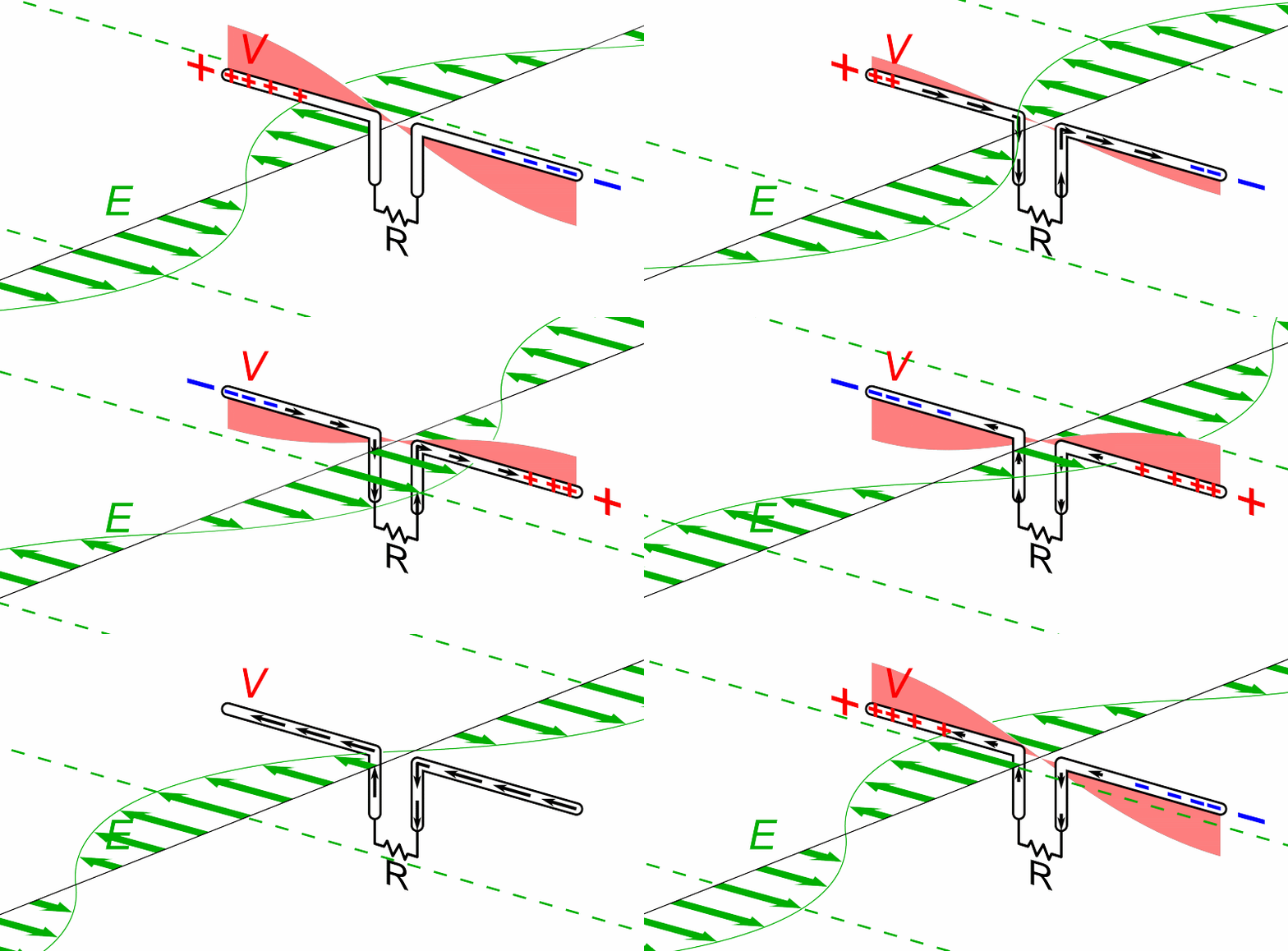
English: Animation showing a half-wave dipole antenna receiving power from a radio wave. The antenna consists of two metal rods each one-quarter of the wavelength long, attached through a parallel transmission line to a resistance R equal to the characteristic impedance of the antenna, representing the receiver. The electromagnetic wave is represented by its electric field (E, green arrows) (it should be kept in mind that the drawing only shows the field along one line, while the radio wave is actually a plane wave and the electric field is actually the same at every point on a plane perpendicular to the direction of motion). The wave's magnetic field is not shown.

The oscillating electric field exerts force on the electrons in the antenna rods , causing them to move back and forth in currents (black arrows) between the ends of the antenna rods, charging the ends of the antenna alternately positive (+) and negative (−). Since the antenna is a half-wavelength long at the radio wave's frequency, it excites standing waves of voltage (V, red) and current in the antenna. The voltage along the antenna elements is represented graphically by a band of red whose thickness at any point is proportional to the magnitude of the voltage. The oscillating currents flowing back and forth from one antenna element to the other, pass down the transmission line and through the radio receiver, represented by R. In this animation the action is shown slowed down drastically; the radio waves received by dipoles actually oscillate back and forth at tens of thousands to billions of cycles per second.
日付
原典 投稿者自身による著作物
作者 Chetvorno
その他のバージョン

Dipole receiving antenna animation 2 800x403x15ms.gif - more wide view

Dipole_receiving_antenna_animation_4_616x380x150ms.gif - shows waves of voltage and current traveling down transmission line
This circuit image could be re-created using vector graphics as an SVG file. This has several advantages; see Commons:Media for cleanup for more information. If an SVG form of this image is available, please upload it and afterwards replace this template with {{vector version available|new image name}}. It is recommended to name the SVG file "Dipole receiving antenna animation 6 800x394x150ms.svg" - then the template Vector version available (or Vva) does not need the new image name parameter.

ライセンス

この作品の著作権者である私は、この作品を以下のライセンスで提供します。
Creative Commons CC-Zero このファイルはクリエイティブ・コモンズ CC0 1.0 全世界 パブリック・ドメイン提供のもとで利用可能にされています。
ある作品に本コモンズ証を関連づけた者は、その作品について世界全地域において著作権法上認められる、その者が持つすべての権利(その作品に関する権利や隣接する権利を含む。)を、法令上認められる最大限の範囲で放棄して、パブリック・ドメインに提供しています。

この作品は、たとえ営利目的であっても、許可を得ずに複製、改変・翻案、配布、上演・演奏することが出来ます。

キャプション

このファイルの内容を1行で記述してください
Animated diagram of a dipole antenna receiving radio waves

このファイルに描写されている項目

題材

7 6 2015

ファイルの履歴

過去の版のファイルを表示するには、その版の日時をクリックしてください。

日付と時刻サムネイル寸法利用者コメント
現在の版2015年6月7日 (日) 07:472015年6月7日 (日) 07:47時点における版のサムネイル800 × 394 (271キロバイト)ChetvornoUser created page with UploadWizard

以下のページがこのファイルを使用しています:

グローバルなファイル使用状況

以下に挙げる他のウィキがこの画像を使っています:

このファイルのグローバル使用状況を表示する。

メタデータ